

Advanced Lane Finding Project
The goals / steps of this project are the following:
The code for this step is contained in the first code cell of the IPython notebook located in “./examples/example.ipynb” (or in lines # through # of the file called some_file.py).
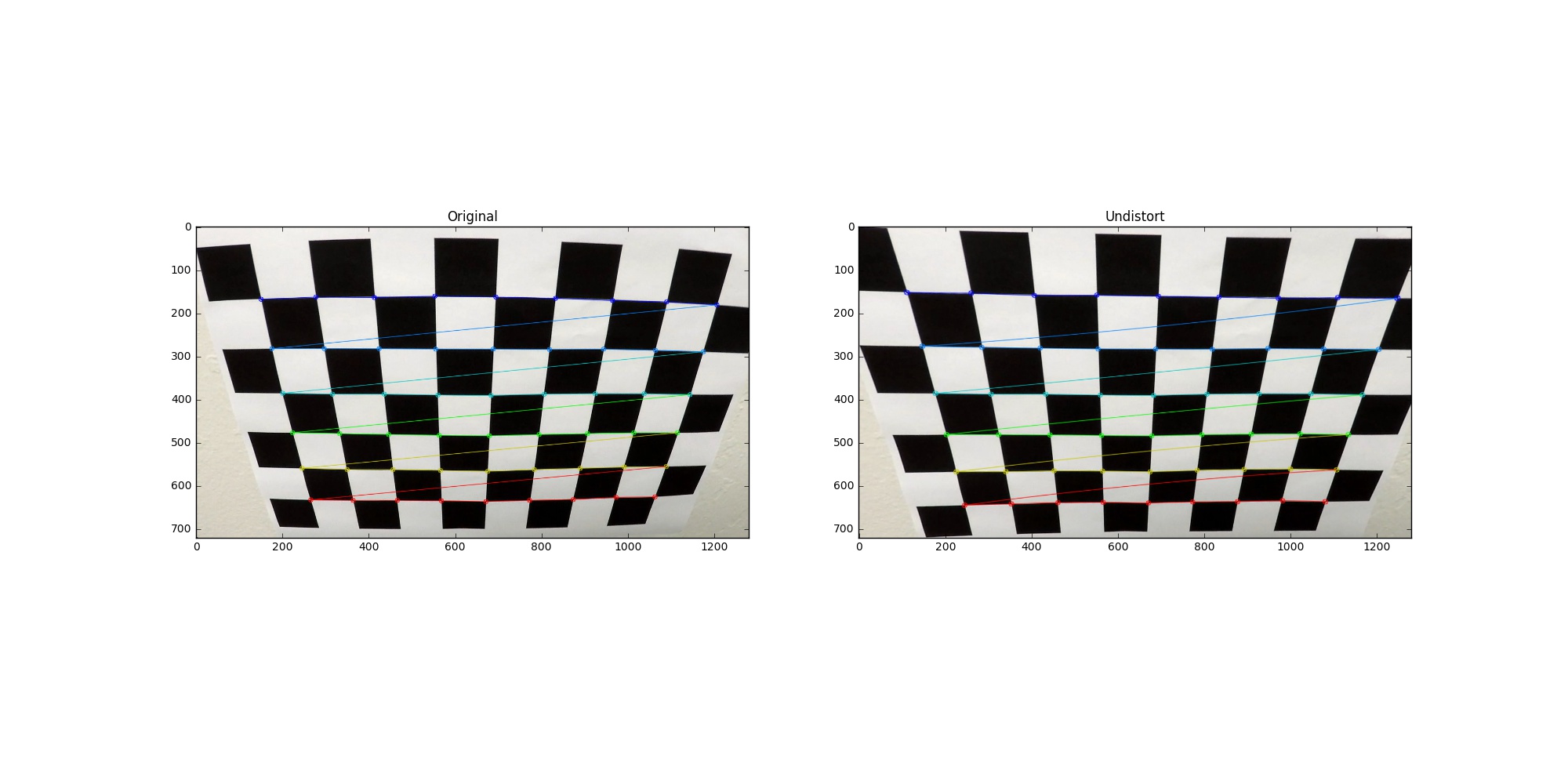
I start by preparing “object points”, which will be the (x, y, z) coordinates of the chessboard corners in the world. Here I am assuming the chessboard is fixed on the (x, y) plane at z=0, such that the object points are the same for each calibration image. Thus, objp is just a replicated array of coordinates, and objpoints will be appended with a copy of it every time I successfully detect all chessboard corners in a test image. imgpoints will be appended with the (x, y) pixel position of each of the corners in the image plane with each successful chessboard detection.
I then used the output objpoints and imgpoints to compute the camera calibration and distortion coefficients using the cv2.calibrateCamera() function. I applied this distortion correction to the test image using the cv2.undistort() function and obtained this result:
To demonstrate this step, I will describe how I apply the distortion correction to one of the test images like this one:
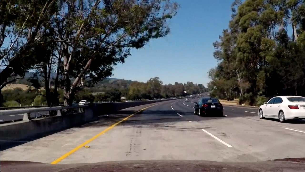
In order to undistort the image, I use cv2.undistort() with distortion coefficients and camera matrix generated by cv2.calibrateCamera().
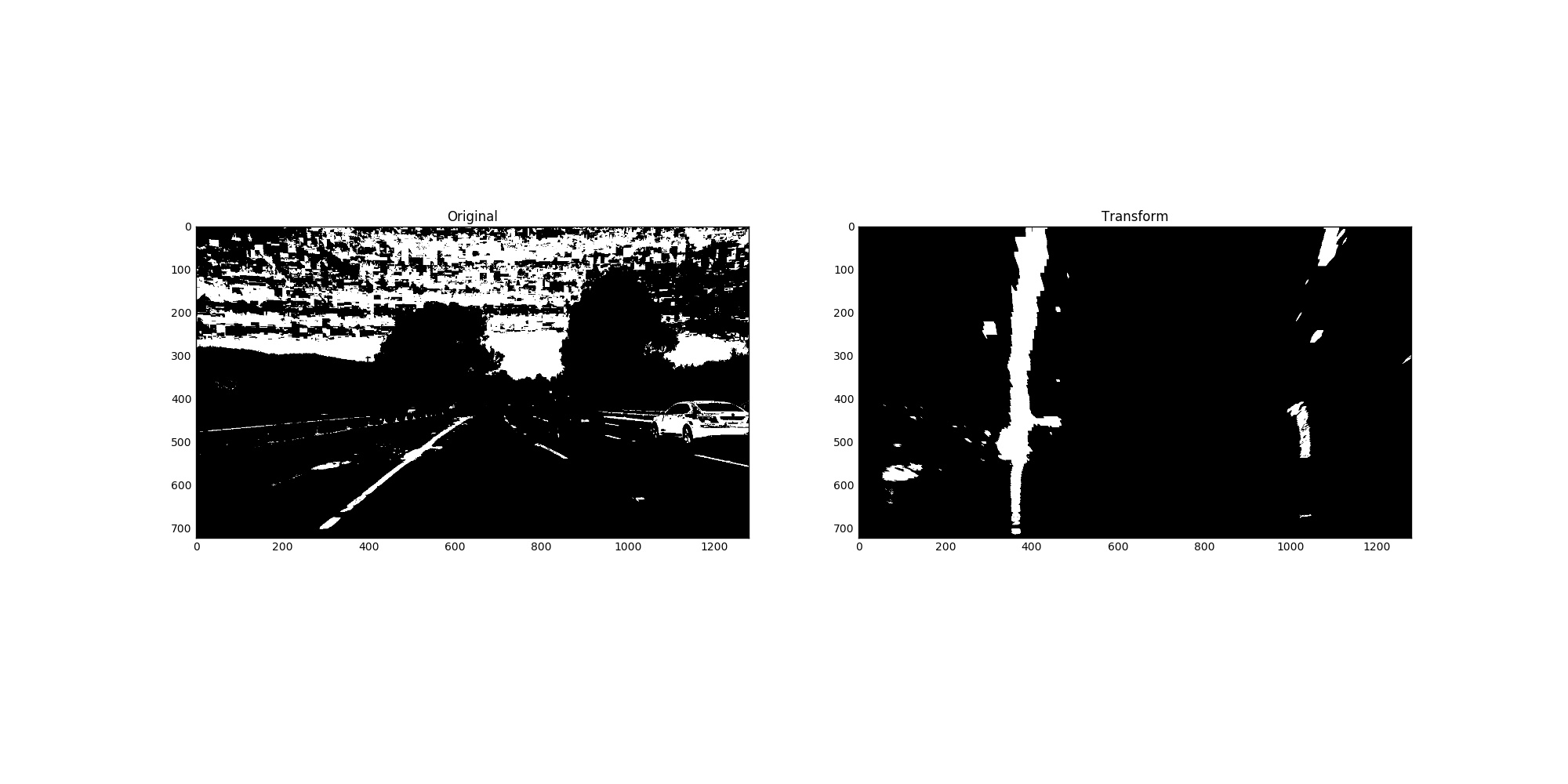
I used a combination of color and gradient thresholds to generate a binary image (thresholding function at lines 32 through 84 in preprocess_utilis.py). Here’s an example of my output for this step.
The code for my perspective transform includes a function called perspective_transform(), which appears in lines 87 through 93 in the file preprocess_utilis.py. The perspective_transform() function takes as inputs source (src) and destination (dst) points and return a transform matrix and its inverse. I chose the hardcode the source and destination points in the following manner:
src = np.float32(
    [[(img_size[0] / 2) - 55, img_size[1] / 2 + 100],
    [((img_size[0] / 6) - 10), img_size[1]],
    [(img_size[0] * 5 / 6) + 60, img_size[1]],
    [(img_size[0] / 2 + 55), img_size[1] / 2 + 100]])
dst = np.float32(
    [[(img_size[0] / 4), 0],
    [(img_size[0] / 4), img_size[1]],
    [(img_size[0] * 3 / 4), img_size[1]],
    [(img_size[0] * 3 / 4), 0]])
This resulted in the following source and destination points:
| Source | Destination |
|---|---|
| 570, 467 | 325, 200 |
| 206, 720 | 325, 720 |
| 715, 467 | 968, 200 |
| 1100, 720 | 968, 720 |
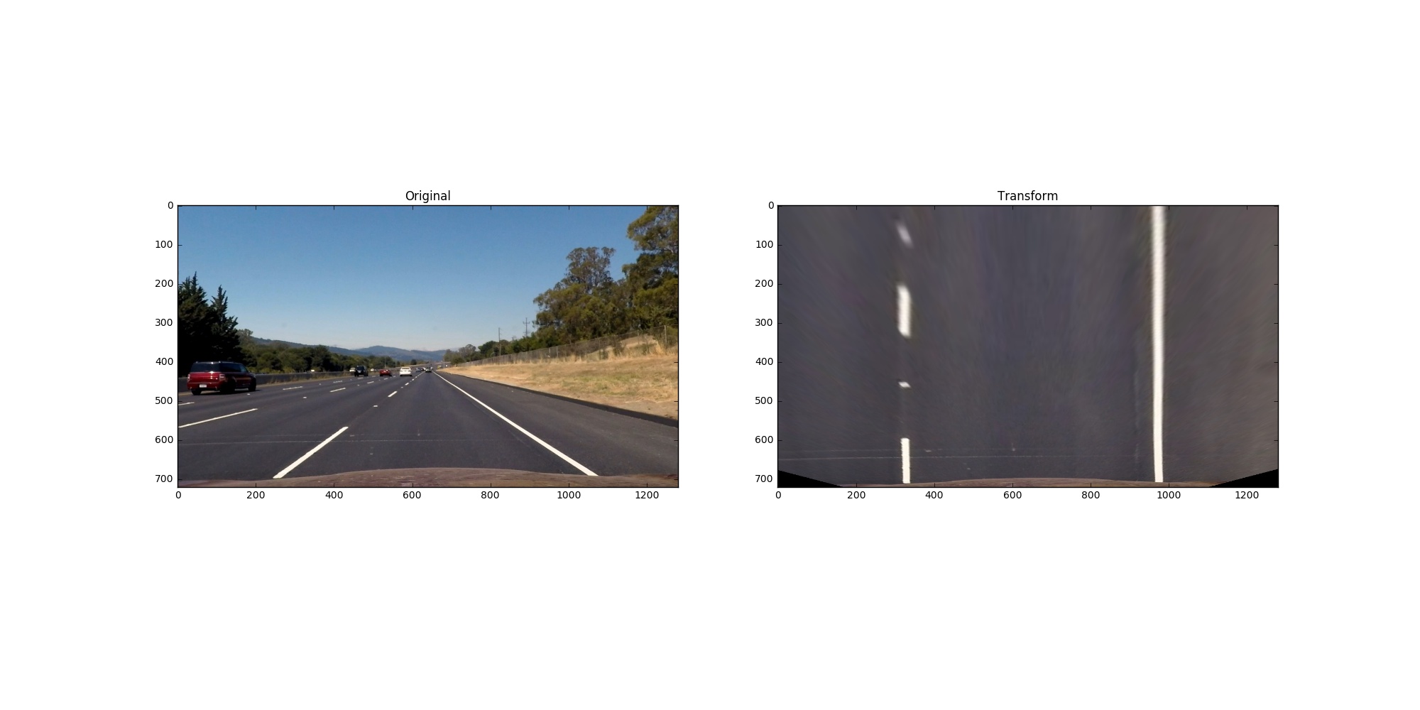
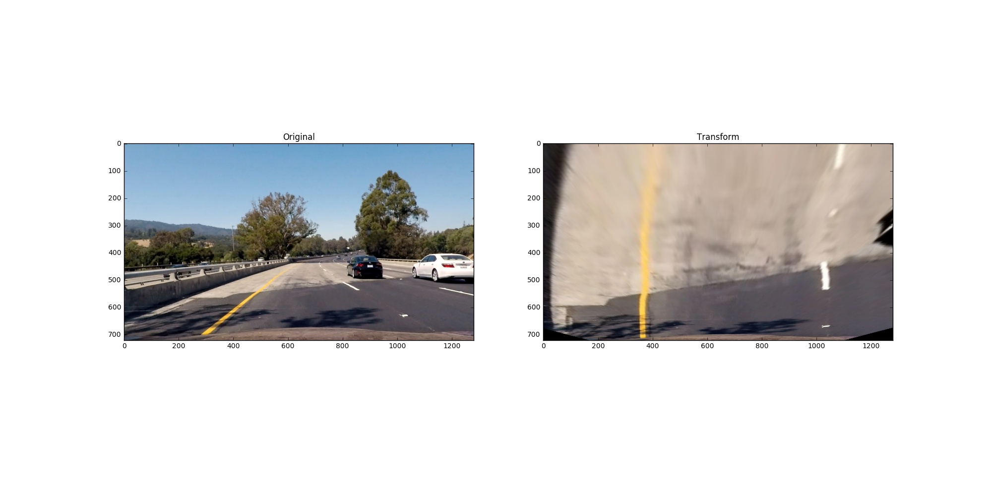
I verified that my perspective transform was working as expected by applying it on both straight lane and curved lane.
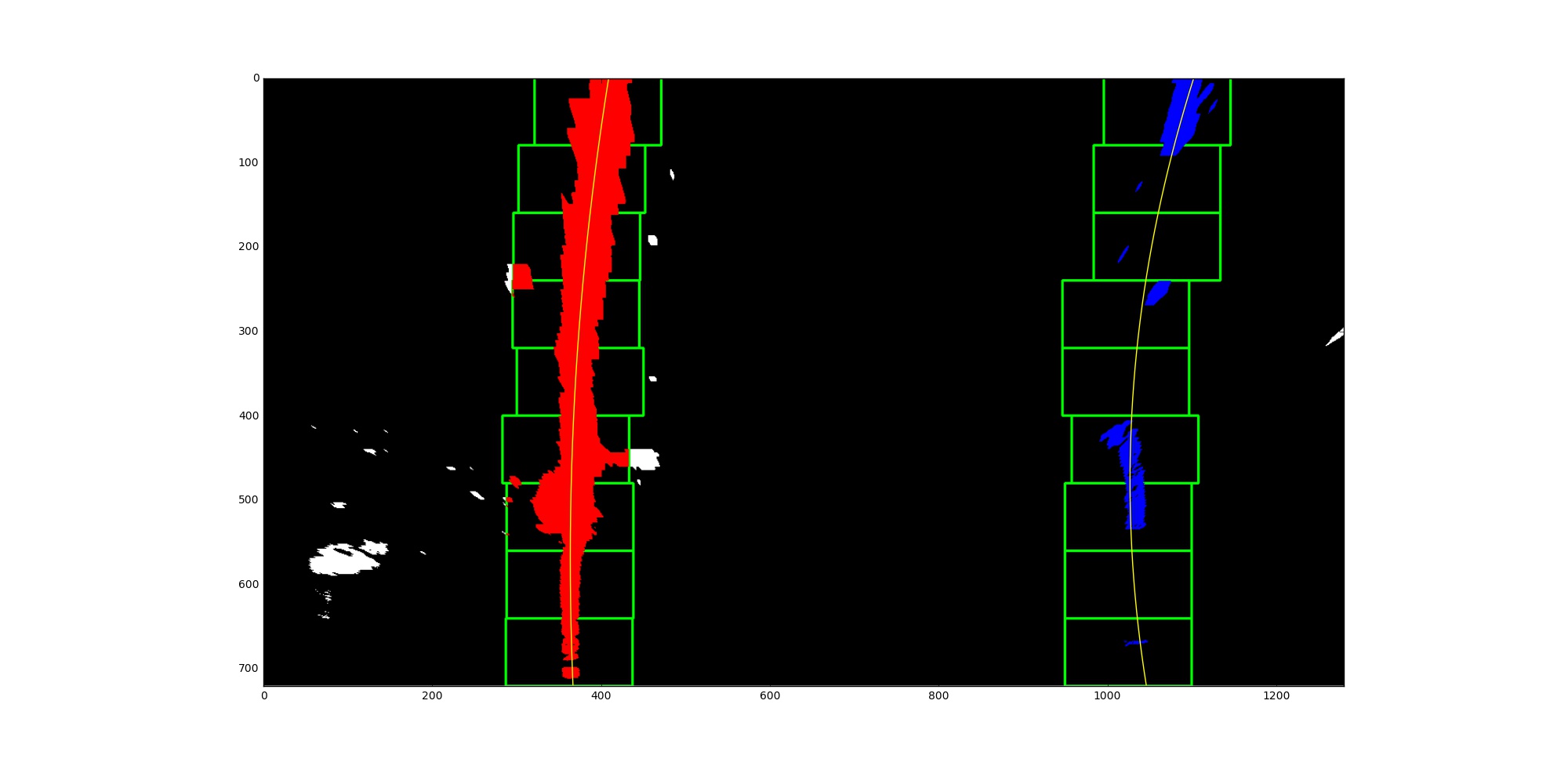
Then I use blind search (blind_search() at line 1 through 71 in findLane.py) if lane wasn’t detected in previous frame, margin search (margin_search() at line 75 through 116 in findLane.py) otherwise to identify lane-line pixels then fit their posistion with polynomial with order 2. If the relative difference between left line’s coefficient and right line’s larger than threshold, I use averaged fitted line of last n qualified lines (findLane() at line 120 through 197 in findLane.py).
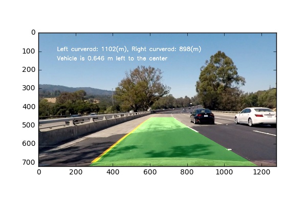
I did this in lines 230 through 251 in my code in findLane.py. First, I refit the line after real-life unit coversion. Then use the equation: (1+(2Ay+B)^2)^(3/2) / abs(2*A) to get the radius of curvature into world space.
I implemented this step in lines 201 through 226 in my code in findLane.py in the function projectLane(). Here is an example of my result on a test image:
Here’s the output for project video
Here’s a the output for the challenge video, it failed when the car fully covered by the bridge.
If you want to reproduce the result, you can use ‘submission.ipynb’.
The the basic idea of this project is to threshold a clean binary map where the search algorithm and easy and correctly identify the lane pixels. The challenges I am facing is when I try to apply the pipeline on the challenge video where some lanes have shadows and dark patchs. The gradient x direction threshold fails me completely when it found many clear vertical lines. The search algorithm has no idea which one is the lane. After trying many things, I abandon gradient. I only use color space thresholding which gives me more stable result in the challenge video. However, it completely fails me again in harder challenge video. Replacing bad result with averaged last n fitted line does help for only one or two bad frame in the row.